
The Designcenter 2606 Mold Wizard release introduces several important enhancements aimed at improving parameter control, streamlining the mold design workflow, and increasing production readiness.
Designcenter Mold Design provides an integrated solution throughout the mold development process, from initial part design and core–cavity–insert creation to standard component placement, verification, and manufacturing data preparation. The platform also connects with product design, simulation, and CAM workflows, helping manufacturers reduce manual tasks, minimize errors, and shorten time to market.
In the 2606 release, the enhancements focus on four key areas:
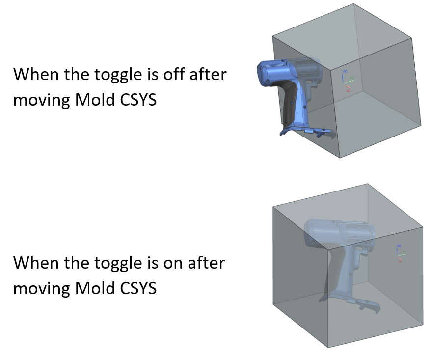
The Mold CSYS – Reset Workpiece feature provides greater control over the workpiece position when users modify the mold coordinate system.
A new Reset Workpiece option has been added to the Mold CSYS settings. Designers can now determine whether the workpiece should be repositioned according to the new coordinate system after the Mold CSYS is moved.
The feature is intelligently enabled based on the workpiece creation method being used and is enabled by default when appropriate.
This enhancement helps:
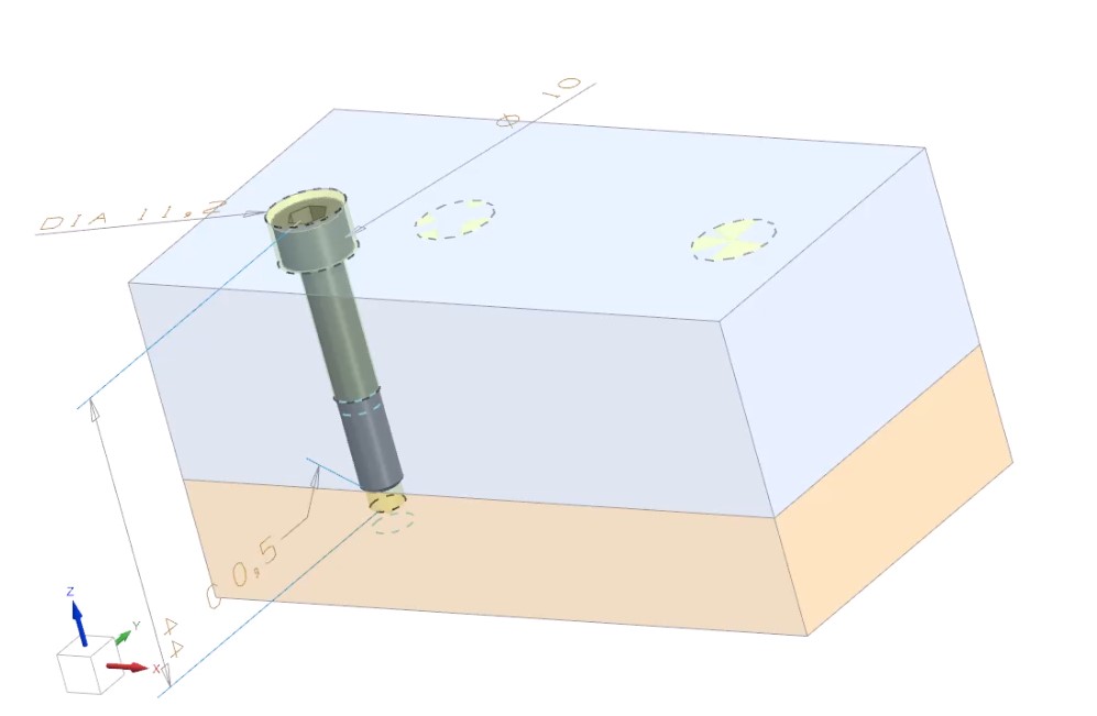
The Pocket – Link PMI Objects feature automatically links PMI information from tool components or standard parts to the target object during pocket creation.
The PMI information may include:
When the source PMI is modified or removed, the linked PMI on the target object is automatically updated accordingly.
This ensures that technical data remains synchronized without affecting geometric operations. It is a valuable enhancement for companies implementing MBD, helping improve document consistency and information traceability throughout the mold design lifecycle.
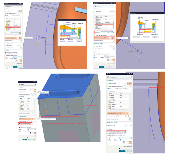
The enhancements in the Vent Enhancements group provide more precise control over the placement and layout of vent paths.
Users can directly create vent holes on the mold surface. The system automatically connects each hole to the nearest secondary vent line, while allowing the hole size to be adjusted through the Vent_Hole_D parameter.
NX 2606 also supports:
These enhancements make vent layout faster and more efficient while maintaining the flexibility to accommodate different mold structures and specific venting requirements.
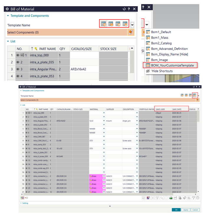
NX 2606 enhances the Bill of Materials (BOM) creation and management process, particularly in template selection and tracking data-saving history.
Users can display BOM templates as visual icons, supporting both default and customized templates. Icons can be defined at multiple resolutions to ensure proper display across different screen types.
The new version also adds automatic export capabilities for:
These details can be displayed directly in the BOM dialog box and included in exported reports. The data is synchronized with the part metadata in read-only mode, improving transparency, accountability, and change traceability.
The Mold Cost Enhancements focus on improving the accuracy and flexibility of mold cost estimation.
The system can automatically adjust the mold base size based on slide complexity through the Mold_Base_Increment configuration logic.
In addition, users can:
Cost data can be managed by categories such as undercuts, mold size, hot runners, and customer requirements. This enables quotations to more accurately reflect the actual configuration of the mold assembly.
.jpg)
.jpg)
.jpg)
The Check Wall Thickness feature now supports displaying results as percentages.
Instead of viewing only absolute wall thickness values, users can evaluate wall thickness based on predefined percentage ranges. When this option is enabled, the results in both the graphics window and dialog box are updated according to the same criteria.
The option status can be saved and automatically restored in subsequent sessions.
This enhancement helps engineers to:
.png)
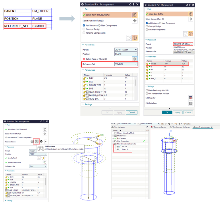
The Standard Part Library has been enhanced to provide greater control over components through spreadsheets, reference sets, and wireframe models.
Users can define component parent relationships directly in the spreadsheet using the PARENT parameter. When spreadsheet data is modified, component relationships are updated accordingly.
NX 2606 also allows users to:
This approach helps reduce model size during the preliminary layout stage while improving display and editing performance for mold assemblies containing a large number of components.
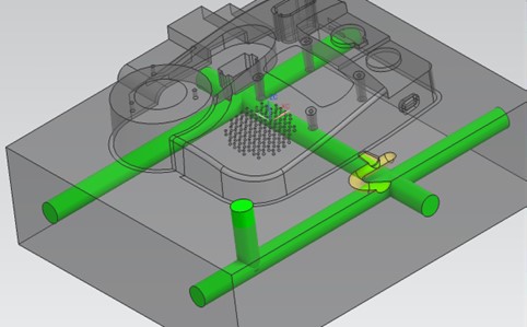
The Direct Channel – Continuous Creation Mode significantly improves the efficiency of designing multiple cooling channels.
With the Continuous Creation option, users can create multiple channels consecutively within a single Apply operation without having to close and reopen the command.
When this mode is enabled, dragging the manipulator automatically creates an additional channel. When disabled, dragging the manipulator only changes the position of the current channel, consistent with the behavior in previous versions.
Continuous Creation is enabled by default to support faster multi-channel creation, reduce repetitive operations, and minimize unnecessary command switching.
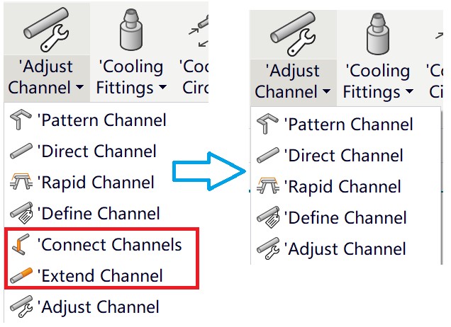
The Extend Channel and Connect Channels tools were previously available as separate commands within the Cooling Tools menu. In NX 2606, both functions are now integrated directly into the Adjust Channel dialog box.
Users can select the required function under Adjust Channel Type while retaining all the capabilities of the original commands.
This enhancement helps to:
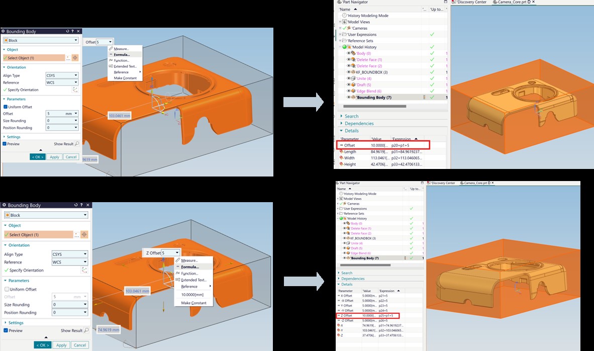
NX 2606 adds the ability to enter formulas and reference expressions directly into the Offset fields of the Bounding Body command.
In Uniform Offset mode, a single expression can control the offset distance in all directions simultaneously. In Non-uniform Offset mode, users can define six independent expressions corresponding to the six offset directions.
This enables bounding geometry to update automatically when design parameters change. It is particularly useful for workflows such as:
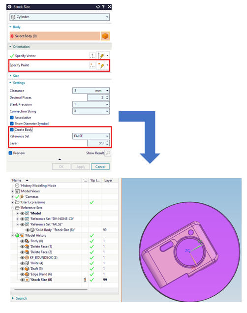
The Stock Size feature has been enhanced to improve the accuracy of stock positioning and automate model organization.
For cylindrical stock, users can specify a specific point through which the stock axis must pass. The new Specify Point option in the Orientation group provides greater control over the stock’s orientation and positioning.
After creation, the blank body can be automatically moved to:
The default setting uses Layer 99, while allowing users to configure the Reference Set name and layer number according to their company’s data management standards.
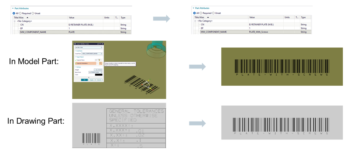
The Insert QR/Bar Code feature has been enhanced to allow codes to be directly linked to part attributes.
Users can create Code Rules based on attribute values. When a linked attribute is changed, the QR Code or Barcode is automatically updated in both the Model Part and Drawing Part environments.
This enhancement supports:
The Plunger Design Enhancements provide greater control over runners, gates, and metal flow.
Runners and gates can be projected onto selected surfaces and accurately subtracted from the mold body, core, or cavity.
The new version supports:
These enhancements improve model stability, enhance runner alignment, and reduce errors when performing Boolean subtraction operations with mold components.
.jpg)
The enhancements in Designcenter 2606 Mold Wizard go beyond adding individual features. They are designed to deliver a more parametric, automated, and highly connected mold design workflow.
The new version helps businesses:
In line with the solution’s overall direction, Designcenter Mold Design can read and modify data from multiple CAD systems, automate workflows based on best practices, and integrate design, simulation, and CAM on a unified technology platform.
Designcenter 2606 Mold Wizard is a major update focused on design productivity, parametric control, and manufacturing readiness.
From Mold CSYS setup, vent creation, standard component management, and wall thickness inspection to channel, runner, gate, and QR Code design, each enhancement helps users reduce manual operations while maintaining greater data consistency.
For mold design and manufacturing companies, 2606 provides a foundation for building faster, more standardized, and more adaptable design workflows, enabling teams to respond more effectively to changes throughout the product development process.